Table of Contents
Memory tutorial for USB-FPGA-Modules 2.12, 2.13, 2.14 and 2.18
This tutorial explains the generation of the memory controller IP Core for for the memfifo Example USB-FPGA-Modules 2.12, USB-FPGA-Modules 2.13, USB-FPGA-Modules 2.14 and USB-FPGA-Modules 2.18.
Creating the IP Core
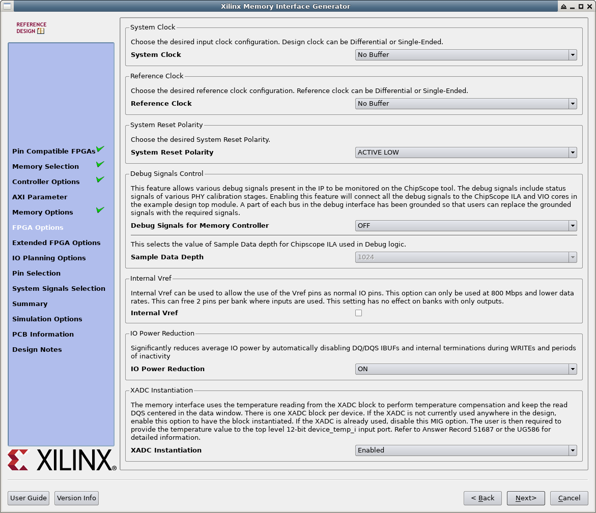
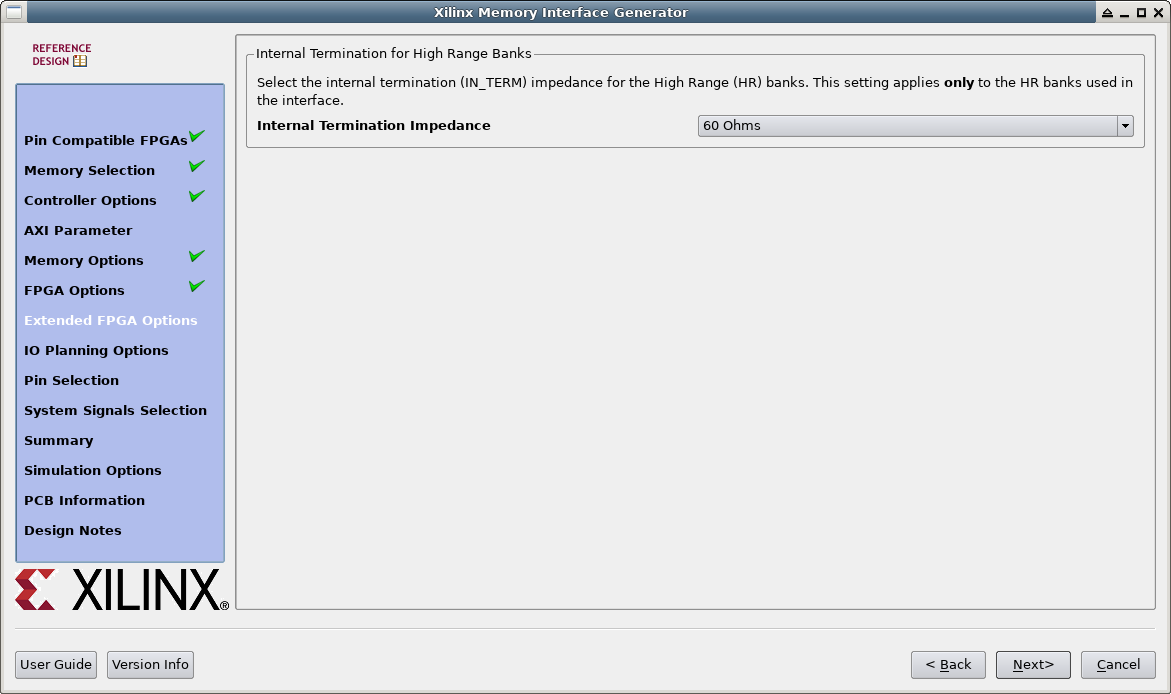
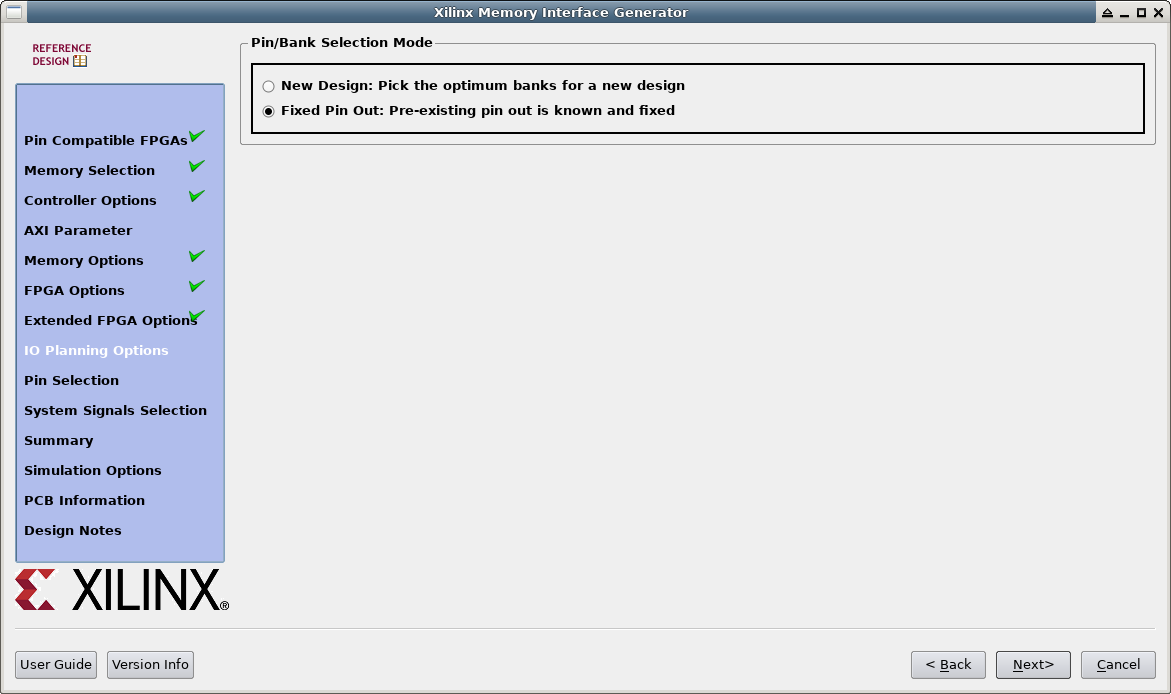
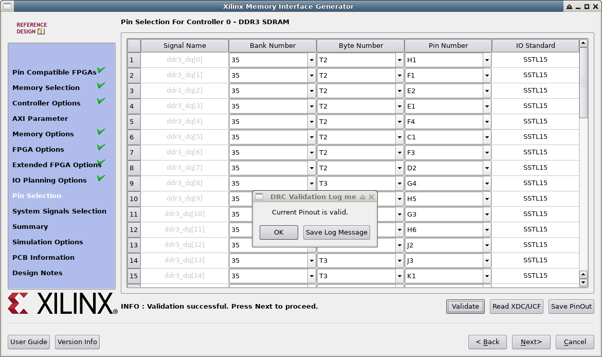
This section describes how the IP Core is created using MIG version 2.1 (Viavado Version 14.2). The settings for other versions should be very similar.
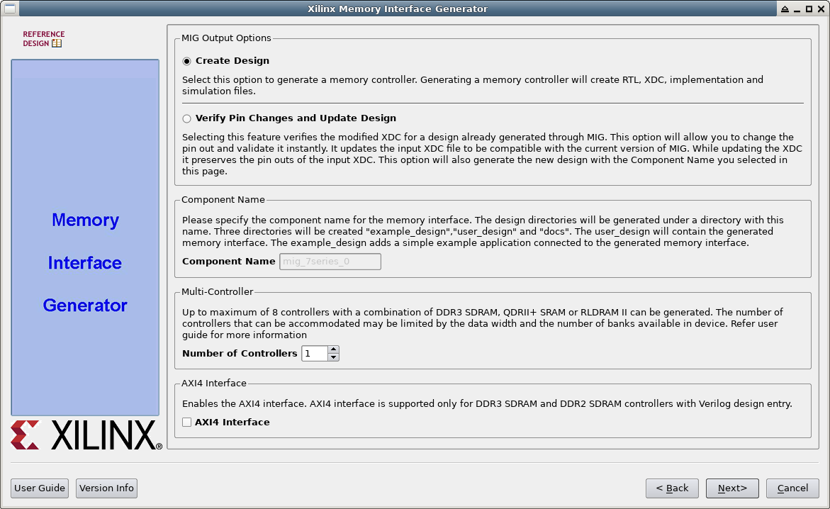
- In the Project Manager: click on
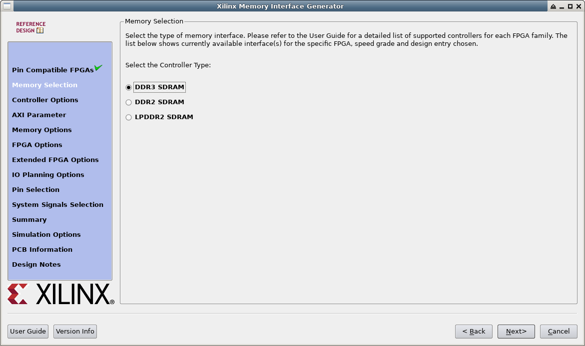
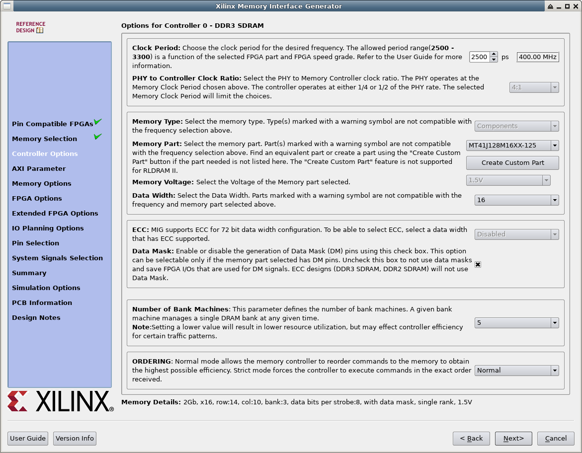
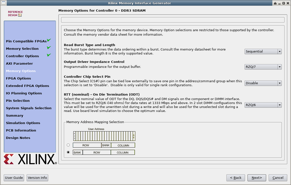
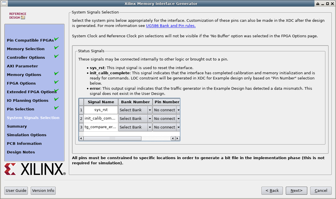
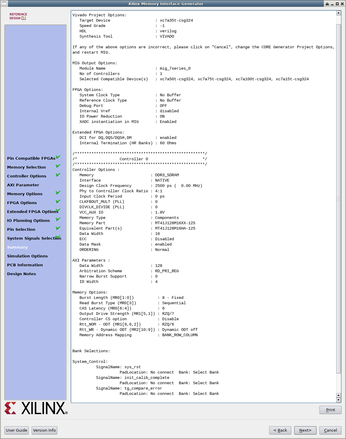
Memories & Storage Elements→Memory Interface Generators→MIG - Verify the Settings in the first dialog box (FPGA type, speed grade, …)
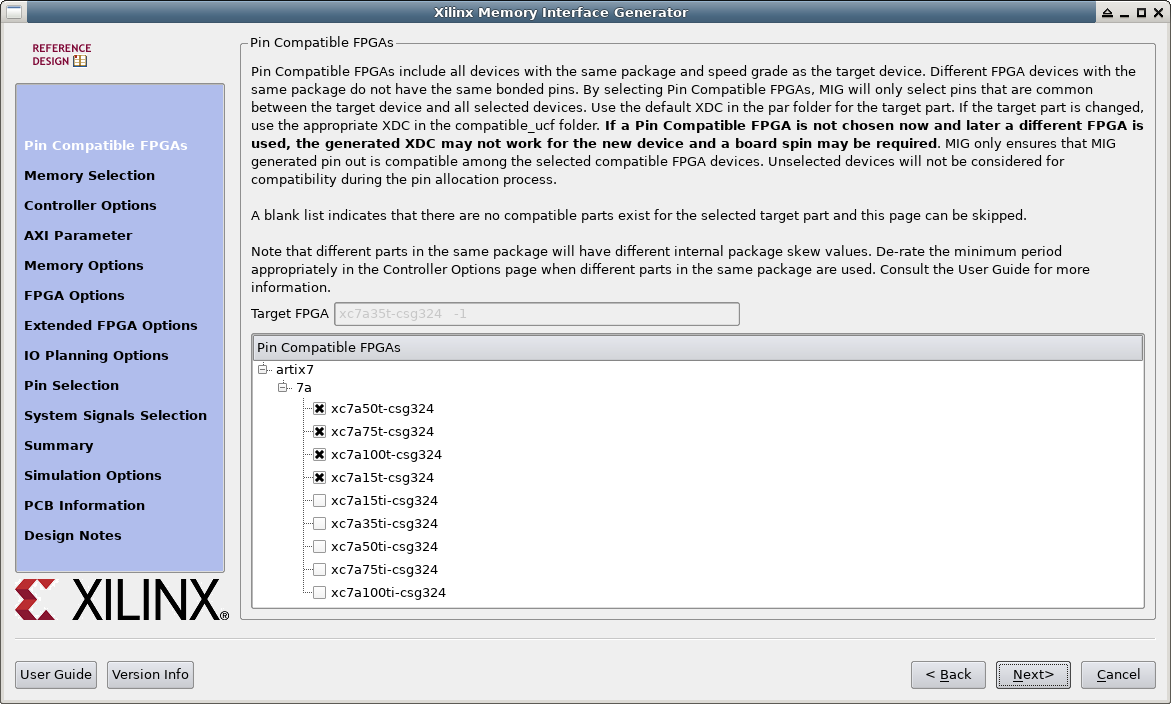
- Here you can chose to create constraints for pin-compatible parts. If you change the part you must replace the constraint file which are a little bit hidden. The constraint for the base part is located in
<project name>.srcs/sources_1/ip/<component name>/<component name>/user_design/constraints/<component name>.xdc. This one needs to be replaced by another one from the directory<project name>.srcs/sources_1/ip/<component name>/<component name>/user_design/constraints/compatible_ucf.
Instantiation of the core
Templates with description for instantiation can be found in the file <project name>.srcs/sources_1/ip/<component name>/<component name>.v[o|h]e
of the Vivado project.
In the memfifo example this looks like
    mig_7series_0   mem0 (
// Memory interface ports
	.ddr3_dq(ddr3_dq),
        .ddr3_dqs_n(ddr3_dqs_n),
        .ddr3_dqs_p(ddr3_dqs_p),
        .ddr3_addr(ddr3_addr),
        .ddr3_ba(ddr3_ba),
        .ddr3_ras_n(ddr3_ras_n),
        .ddr3_cas_n(ddr3_cas_n),
        .ddr3_we_n(ddr3_we_n),
        .ddr3_reset_n(ddr3_reset_n),
        .ddr3_ck_p(ddr3_ck_p[0]),
        .ddr3_ck_n(ddr3_ck_n[0]),
        .ddr3_cke(ddr3_cke[0]),
	.ddr3_dm(ddr3_dm),
        .ddr3_odt(ddr3_odt[0]),
// Application interface ports
        .app_addr( {1'b0, app_addr, 3'b000} ),
        .app_cmd(app_cmd),
        .app_en(app_en),
        .app_rdy(app_rdy),
        .app_wdf_rdy(app_wdf_rdy),
        .app_wdf_data(app_wdf_data),
        .app_wdf_mask({ APP_MASK_WIDTH {1'b0} }),
        .app_wdf_end(app_wdf_wren), // always the last word in 4:1 mode
        .app_wdf_wren(app_wdf_wren),
        .app_rd_data(app_rd_data),
        .app_rd_data_end(app_rd_data_end),
        .app_rd_data_valid(app_rd_data_valid),
        .app_sr_req(1'b0),
        .app_sr_active(),
        .app_ref_req(1'b0),
        .app_ref_ack(),
        .app_zq_req(1'b0),
        .app_zq_ack(),
        .ui_clk(uiclk),
        .ui_clk_sync_rst(ui_clk_sync_rst),
        .init_calib_complete(init_calib_complete),
        .sys_rst(!reset),
// clocks inputs
        .sys_clk_i(clk400),
        .clk_ref_i(clk200)
    );
Clocks on USB-FPGA Modules 2.13
On USB-FPGA Modules 2.13 the clock are generated on-chip from the 48 MHz output clock of the EZ-USB. A PLLE2 is recommended for this purpose as used in the memfifo example:
    wire pll_fb, clk200, clk400, uiclk, fxclk;

    BUFG fxclk_buf (
	.I(fxclk_in),
 	.O(fxclk)
    );

    PLLE2_BASE #(
    	.BANDWIDTH("LOW"),
      	.CLKFBOUT_MULT(25),       		// f_VCO = 1200 MHz (valid: 800 .. 1600 MHz)
      	.CLKFBOUT_PHASE(0.0),
      	.CLKIN1_PERIOD(0.0),
      	.CLKOUT0_DIVIDE(3),			// 400 MHz, memory clock
       	.CLKOUT1_DIVIDE(6),			// 200 MHz, reference clock
      	.CLKOUT2_DIVIDE(CLKOUT2_DIVIDE), 	// unused
      	.CLKOUT3_DIVIDE(CLKOUT3_DIVIDE), 	// unused
       	.CLKOUT4_DIVIDE(CLKOUT4_DIVIDE), 	// unused
      	.CLKOUT5_DIVIDE(CLKOUT5_DIVIDE), 	// unused
      	.CLKOUT0_DUTY_CYCLE(0.5),
      	.CLKOUT1_DUTY_CYCLE(0.5),
      	.CLKOUT2_DUTY_CYCLE(0.5),
      	.CLKOUT3_DUTY_CYCLE(0.5),
       	.CLKOUT4_DUTY_CYCLE(0.5),
      	.CLKOUT5_DUTY_CYCLE(0.5),
      	.CLKOUT0_PHASE(0.0),
      	.CLKOUT1_PHASE(0.0),
      	.CLKOUT2_PHASE(CLKOUT2_PHASE),
      	.CLKOUT3_PHASE(CLKOUT3_PHASE),
       	.CLKOUT4_PHASE(CLKOUT4_PHASE),
      	.CLKOUT5_PHASE(CLKOUT5_PHASE),
       	.DIVCLK_DIVIDE(1),
      	.REF_JITTER1(0.0),
      	.STARTUP_WAIT("FALSE")
    )
    dram_fifo_pll_inst (
      	.CLKIN1(fxclk),		// 48 MHz input clock
      	.CLKOUT0(clk400),	// 400 MHz memory clock
      	.CLKOUT1(clk200),       // 200 MHz reference clock
      	.CLKOUT2(),
      	.CLKOUT3(),
      	.CLKOUT4(),
      	.CLKOUT5(),
      	.CLKFBOUT(pll_fb),
      	.CLKFBIN(pll_fb),
      	.PWRDWN(1'b0),
      	.RST(1'b0)
    );
Clocks on USB-FPGA Modules 2.14 and 2.18
On USB-FPGA Modules 2.14 and 2.18 the clock are generated on-chip from the 26 MHz on-bord oscilator. A PLLE2 is recommended for this purpose as used in the memfifo example:
    wire pll_fb, clk200, clk400, uiclk, fxclk;
    wire pll_fb, clk200_in, clk400_in, clk200, clk400, uiclk, fxclk;

    BUFG fxclk_buf (
	.I(fxclk_in),
	.O(fxclk)
    );

    BUFG clk200_buf (  		// sometimes it is generated automatically, sometimes not ...
	.I(clk200_in),
	.O(clk200)
    );

    BUFG clk400_buf (
	.I(clk400_in),
	.O(clk400)
    );

    PLLE2_BASE #(
    	.BANDWIDTH("LOW"),
      	.CLKFBOUT_MULT(31),     // f_VCO = 806 MHz (valid: 800 .. 1600 MHz)
      	.CLKFBOUT_PHASE(0.0),
      	.CLKIN1_PERIOD(0.0),
      	.CLKOUT0_DIVIDE(2),	// 403 Mz
      	.CLKOUT1_DIVIDE(4),	// 201.5 MHz
      	.CLKOUT2_DIVIDE(CLKOUT2_DIVIDE),
      	.CLKOUT3_DIVIDE(CLKOUT3_DIVIDE),
      	.CLKOUT4_DIVIDE(CLKOUT4_DIVIDE),
      	.CLKOUT5_DIVIDE(CLKOUT5_DIVIDE),
      	.CLKOUT0_DUTY_CYCLE(0.5),
      	.CLKOUT1_DUTY_CYCLE(0.5),
      	.CLKOUT2_DUTY_CYCLE(0.5),
      	.CLKOUT3_DUTY_CYCLE(0.5),
      	.CLKOUT4_DUTY_CYCLE(0.5),
      	.CLKOUT5_DUTY_CYCLE(0.5),
      	.CLKOUT0_PHASE(0.0),
      	.CLKOUT1_PHASE(0.0),
      	.CLKOUT2_PHASE(CLKOUT2_PHASE),
      	.CLKOUT3_PHASE(CLKOUT3_PHASE),
      	.CLKOUT4_PHASE(CLKOUT4_PHASE),
      	.CLKOUT5_PHASE(CLKOUT5_PHASE),
      	.DIVCLK_DIVIDE(1),
      	.REF_JITTER1(0.0),
      	.STARTUP_WAIT("FALSE")
    )
    dram_fifo_pll_inst (
      	.CLKIN1(fxclk),
      	.CLKOUT0(clk400_in),
      	.CLKOUT1(clk200_in),
      	.CLKOUT2(clkout2),
      	.CLKOUT3(clkout3),
      	.CLKOUT4(clkout4),
      	.CLKOUT5(clkout5),
      	.CLKFBOUT(pll_fb),
      	.CLKFBIN(pll_fb),
      	.PWRDWN(1'b0),
      	.RST(1'b0)
    );
