This is an old revision of the document!
Table of Contents
Cluster Power Supplies
Because ZTEX FPGA Board communicate via USB it is easily possible to build low cost FPGA clusters using USB hubs. For this purpose typically USB-FPGA Modules 1.15x, USB-FPGA Modules 1.15y or USB-FPGA Modules 1.15d (if RAM is required) are used.
This article presents some suggestions for the power supply of such FPGA Board Clusters.
USB-FPGA Module 1.15x and 1.15d: Small clusters
Small clusters can easily powered using 12V/5A switching supplies and DC splitter cables. These PSU's can power up to 5 FPGA Boards. All required components are available form the online shop:
USB-FPGA Module 1.15x and 1.15d: Large clusters
For larger FPGA clusters high efficient ATX PSU's with plugable cables are the best choice. The following guide explains how such a PSU can be modified for an FPGA cluster.
Requirements:
- ATX PSU
- power cables with 2.1/5.5mm plug for the FPGA boards, e.g. from http://search.digikey.com/scripts/DkSearch/dksus.dll?KeyWords=CP-2189-ND. Center pin wire (+12V) is marked with a white stripe
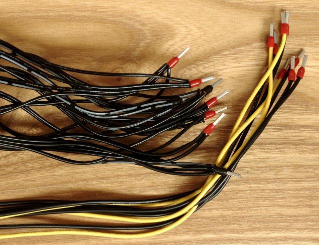
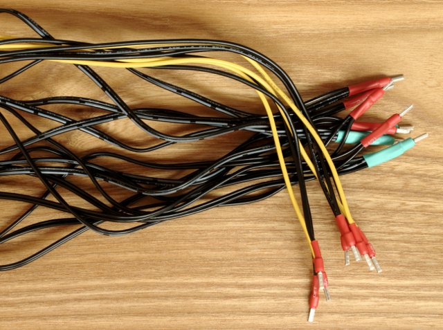
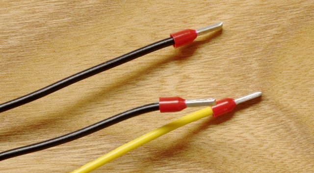
- bootlace ferrules and a crimp tool (e.g. from Ebay)
- luster terminal (e.g. from Ebay)
- heat shrink tubing (optional, e.g from Ebay)
Procedure:
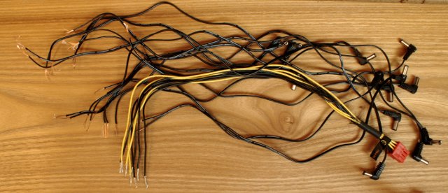
- Connect FPGA board power cables (the ones with the 2.1/5.5mm plug) to the cables from PSU. GND wires from PSU (black) should not power more than 3 FPGA Boards and +12V wires (yellow) should not power more than 5 FPGA Boards. (GND wires are more critical in order to reduce current flows through USB cable)
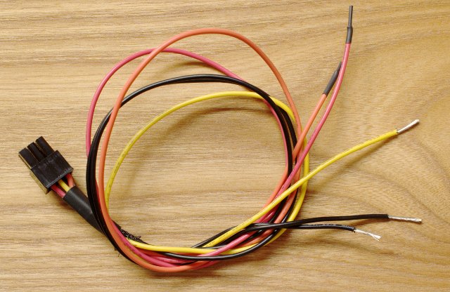
- Cut off the HD connector / GPU connector / ATX12V connector (i.e. not the to-PSU plug) from the PSU cable and cut FPGA power cables to the desired length.
- Connect the cables from PSU to FPGA power cable using the luster terminal. In the picture each GND wire from the PSU is connected to 3 GND wires to FPGA Board and each +12V wire is connected to 5 +12V wires to FPGA Board, i.e. all together 15 power cables to FPGA boards are connected to 3 +12V wires and 5 GND wires from PSU (was a GPU cable).
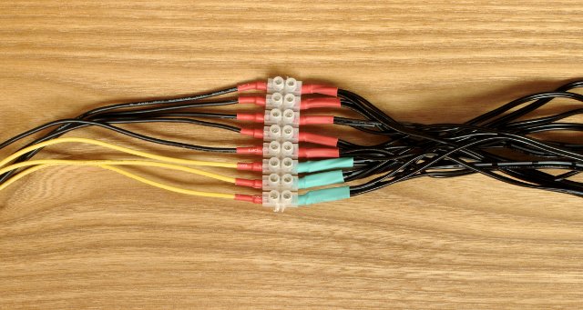
- Connect the “Power on” (green wire) signal to a GND wire (black), see http://en.wikipedia.org/wiki/ATX#Power_supply. Bootlace ferrules and luster terminals can be used as above. Then the PSU is powered on and off using the switch on the rear side of the PSU. Alternatively, a switch can be connected to the the green and a black wire. In this case the switch powers the FPGA cluster on and off.
USB-FPGA Modules 1.15y: Small clusters
For small clusters 12V/4A or more switching PSU's can be used to power one Quad FPGA Boards. These PSU are connected to CON3
Suitable PSU's are available in the online shop:
USB-FPGA Modules 1.15y: Large clusters
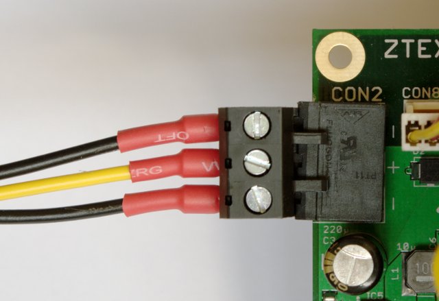
For larger FPGA clusters high efficient ATX PSU's with plugable cables are the best choice. These PSU can be easily modified to power the Quad FPGA Baords using CON2:
Requirements:
- ATX PSU
- bootlace ferrules and a crimp tool (e.g. from Ebay)
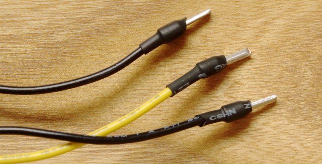
- heat shrink tubing (optional, e.g from Ebay)
Procedure:
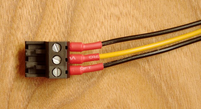
- Connect the plugable terminal block of CON2 to the cables from PSU. Two GND wires (black, one if AWG16 cable is also sufficient) and +12V wires (yellow) are required. (GND wires are more critical in order to reduce current flows through USB cable)
- Cut off the HD connector / GPU connector / ATX12V connector (i.e. not the to-PSU plug) from the PSU cable and cut FPGA power cables to the desired length.
- Connect the “Power on” (green wire) signal to a GND wire (black), see http://en.wikipedia.org/wiki/ATX#Power_supply. Bootlace ferrules and luster terminals can be used. Then the PSU is powered on and off using the switch on the rear side of the PSU. Alternatively, a switch can be connected to the the green and a black wire. In this case the switch powers the FPGA cluster on and off.
