Table of Contents
Memory tutorial for USB-FPGA-Modules 2.04
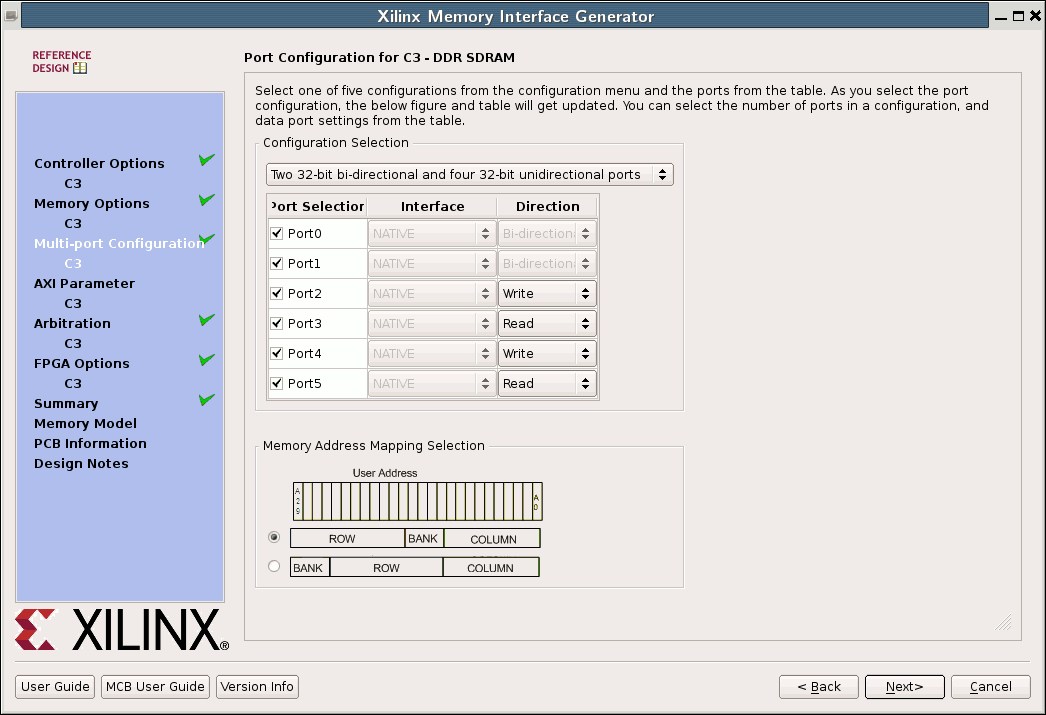
This tutorial explains the generation of the memory controller IP Core for for the memfifo Example USB-FPGA-Modules 2.04.
Creating the IP Core
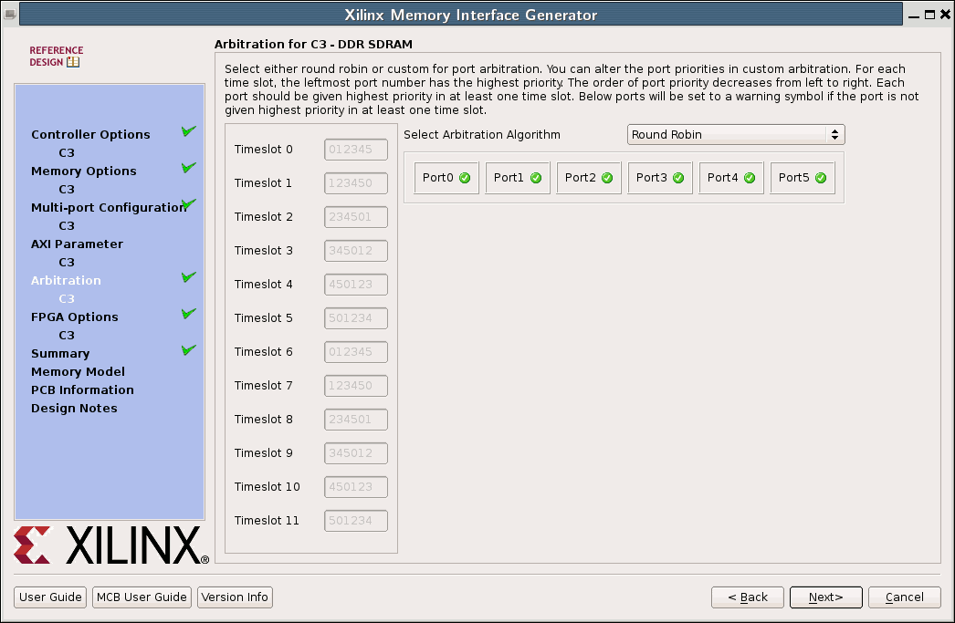
This section describes how the IP Core is created using MIG version 13.41 (ISE Version 14.7). The settings for other versions should be very similar.
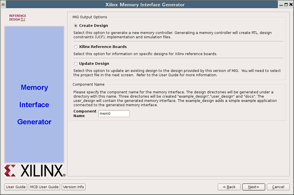
- In the menu:
Project→New Source - Choose
IP Core Generatorand enter a name for the new Core - Select
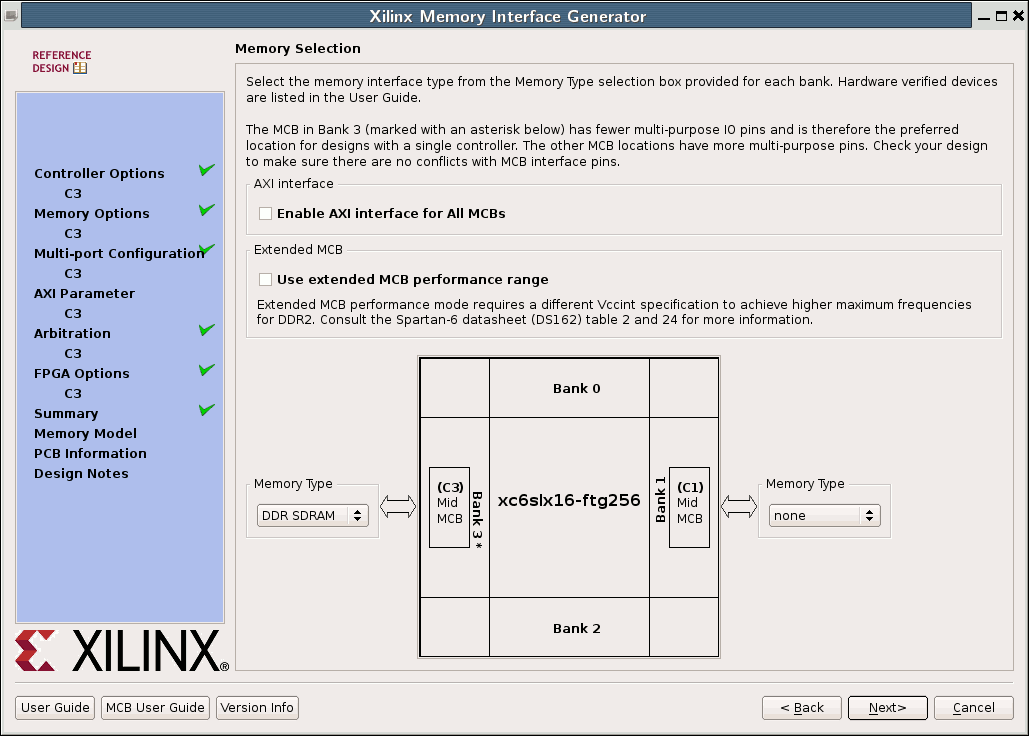
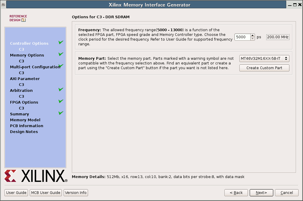
Memories & Storage Elements→Memory Interface Generators→MIGand click onNEXT→FINISH - Verify the Settings in the first dialog box (FPGA type, speed grade, …)
- The settings on the next screen (pin compatible devices) can be ignored, because design of the FPGA Board is fixed
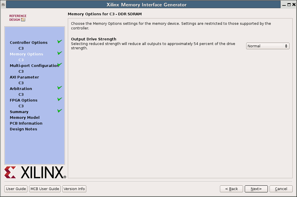
- Click
NEXTon the following dialog boxes andGenerateon the last screen.
Instantiation of the core
Templates with description for instantiation can be found in the file *ipcore_dir/<component name>.v[o|h]e
of the ISE project.
In the memfifo example this looks like
   mem0 # (
	.C3_P0_MASK_SIZE(4),
	.C3_P0_DATA_PORT_SIZE(32),
	.C3_P1_MASK_SIZE(4),
    	.C3_P1_DATA_PORT_SIZE(32),
    	.DEBUG_EN(0),
    	.C3_MEMCLK_PERIOD(5000),
    	.C3_CALIB_SOFT_IP("TRUE"),
    	.C3_SIMULATION("FALSE"),
    	.C3_RST_ACT_LOW(0),
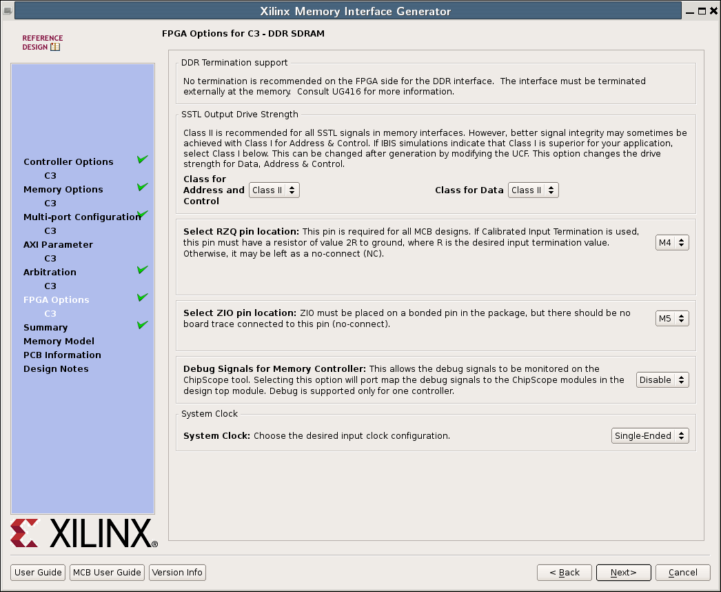
    	.C3_INPUT_CLK_TYPE("SINGLE_ENDED"),
    	.C3_MEM_ADDR_ORDER("ROW_BANK_COLUMN"),
    	.C3_NUM_DQ_PINS(16),
    	.C3_MEM_ADDR_WIDTH(13),
    	.C3_MEM_BANKADDR_WIDTH(2)
    )
    u_mem0 (
  	.mcb3_dram_dq           (ddr_dram_dq),
  	.mcb3_dram_a            (ddr_dram_a),
  	.mcb3_dram_ba           (ddr_dram_ba),
  	.mcb3_dram_ras_n        (ddr_dram_ras_n),
  	.mcb3_dram_cas_n        (ddr_dram_cas_n),
  	.mcb3_dram_we_n         (ddr_dram_we_n),
  	.mcb3_dram_cke          (ddr_dram_cke),
  	.mcb3_dram_ck           (ddr_dram_ck),
  	.mcb3_dram_ck_n         (ddr_dram_ck_n),
  	.mcb3_dram_dqs          (ddr_dram_dqs),
  	.mcb3_dram_udqs         (ddr_dram_udqs),    // for X16 parts
  	.mcb3_dram_udm          (ddr_dram_udm),     // for X16 parts
  	.mcb3_dram_dm           (ddr_dram_dm),
      	.mcb3_rzq               (ddr_rzq),

  	.c3_clk0	        (),
  	.c3_calib_done  	(c3_calib_done),
  	.c3_rst0	        (c3_rst0),
    	.c3_sys_clk           	(memclk),
  	.c3_sys_rst_i           (reset0),

     	.c3_p0_cmd_clk          (WRCLK),
   	.c3_p0_cmd_en           (WR_CMD_EN[0]),
   	.c3_p0_cmd_instr        (3'b000),
   	.c3_p0_cmd_bl           (6'd63),
   	.c3_p0_cmd_byte_addr    ( {4'd0, WR_ADDR, 8'd0} ),
   	.c3_p0_cmd_empty        (),
   	.c3_p0_cmd_full         (),
   	.c3_p0_wr_clk           (WRCLK),
   	.c3_p0_wr_en            (WR_EN[0]),
   	.c3_p0_wr_mask          (4'd0),
   	.c3_p0_wr_data          (WR_DATA),
   	.c3_p0_wr_full          (WR_FULL[0]),
   	.c3_p0_wr_empty         (WR_EMPTY[0]),
   	.c3_p0_wr_count         (),
   	.c3_p0_wr_underrun      (WR_UNDERRUN[0]),
   	.c3_p0_wr_error         (WR_ERROR[0]),
   	.c3_p0_rd_clk           (WRCLK),
   	.c3_p0_rd_en            (1'b0),
   	.c3_p0_rd_data          (),
   	.c3_p0_rd_full          (),
   	.c3_p0_rd_empty         (),
   	.c3_p0_rd_count         (),
   	.c3_p0_rd_overflow      (),
   	.c3_p0_rd_error         (),

   	.c3_p1_cmd_clk          (RDCLK),
   	.c3_p1_cmd_en           (RD_CMD_EN[0]),
   	.c3_p1_cmd_instr        (3'b001),
   	.c3_p1_cmd_bl           (6'd63),
   	.c3_p1_cmd_byte_addr    ( {4'd0, RD_ADDR, 8'd0} ),
   	.c3_p1_cmd_empty        (),
   	.c3_p1_cmd_full         (),
   	.c3_p1_wr_clk           (RDCLK),
   	.c3_p1_wr_en            (1'b0),
   	.c3_p1_wr_mask          (4'd0),
   	.c3_p1_wr_data          (32'd0),
   	.c3_p1_wr_full          (),
   	.c3_p1_wr_empty         (),
   	.c3_p1_wr_count         (),
   	.c3_p1_wr_underrun      (),
   	.c3_p1_wr_error         (),
   	.c3_p1_rd_clk           (RDCLK),
   	.c3_p1_rd_en            (RD_EN[0]),
   	.c3_p1_rd_data          (RD_DATA[0]),
   	.c3_p1_rd_full          (),
   	.c3_p1_rd_empty         (RD_EMPTY[0]),
   	.c3_p1_rd_count         (),
   	.c3_p1_rd_overflow      (RD_OVERFLOW[0]),
   	.c3_p1_rd_error         (RD_ERROR[0]),

     	.c3_p2_cmd_clk          (WRCLK),
   	.c3_p2_cmd_en           (WR_CMD_EN[1]),
   	.c3_p2_cmd_instr        (3'b000),
   	.c3_p2_cmd_bl           (6'd63),
   	.c3_p2_cmd_byte_addr    ( {4'd0, WR_ADDR, 8'd0} ),
   	.c3_p2_cmd_empty        (),
   	.c3_p2_cmd_full         (),
   	.c3_p2_wr_clk           (WRCLK),
   	.c3_p2_wr_en            (WR_EN[1]),
   	.c3_p2_wr_mask          (4'd0),
   	.c3_p2_wr_data          (WR_DATA),
   	.c3_p2_wr_full          (WR_FULL[1]),
   	.c3_p2_wr_empty         (WR_EMPTY[1]),
   	.c3_p2_wr_count         (),
   	.c3_p2_wr_underrun      (WR_UNDERRUN[1]),
   	.c3_p2_wr_error         (WR_ERROR[1]),

   	.c3_p3_cmd_clk          (RDCLK),
   	.c3_p3_cmd_en           (RD_CMD_EN[1]),
   	.c3_p3_cmd_instr        (3'b001),
   	.c3_p3_cmd_bl           (6'd63),
   	.c3_p3_cmd_byte_addr    ( {4'd0, RD_ADDR, 8'd0} ),
   	.c3_p3_cmd_empty        (),
   	.c3_p3_cmd_full         (),
   	.c3_p3_rd_clk           (RDCLK),
   	.c3_p3_rd_en            (RD_EN[1]),
   	.c3_p3_rd_data          (RD_DATA[1]),
   	.c3_p3_rd_full          (),
   	.c3_p3_rd_empty         (RD_EMPTY[1]),
   	.c3_p3_rd_count         (),
   	.c3_p3_rd_overflow      (RD_OVERFLOW[1]),
   	.c3_p3_rd_error         (RD_ERROR[1]),

     	.c3_p4_cmd_clk          (WRCLK),
   	.c3_p4_cmd_en           (WR_CMD_EN[2]),
   	.c3_p4_cmd_instr        (3'b000),
   	.c3_p4_cmd_bl           (6'd63),
   	.c3_p4_cmd_byte_addr    ( {4'd0, WR_ADDR, 8'd0} ),
   	.c3_p4_cmd_empty        (),
   	.c3_p4_cmd_full         (),
   	.c3_p4_wr_clk           (WRCLK),
   	.c3_p4_wr_en            (WR_EN[2]),
   	.c3_p4_wr_mask          (4'd0),
   	.c3_p4_wr_data          (WR_DATA),
   	.c3_p4_wr_full          (WR_FULL[2]),
   	.c3_p4_wr_empty         (WR_EMPTY[2]),
   	.c3_p4_wr_count         (),
   	.c3_p4_wr_underrun      (WR_UNDERRUN[2]),
   	.c3_p4_wr_error         (WR_ERROR[2]),

   	.c3_p5_cmd_clk          (RDCLK),
   	.c3_p5_cmd_en           (RD_CMD_EN[2]),
   	.c3_p5_cmd_instr        (3'b001),
   	.c3_p5_cmd_bl           (6'd63),
   	.c3_p5_cmd_byte_addr    ( {4'd0, RD_ADDR, 8'd0} ),
   	.c3_p5_cmd_empty        (),
   	.c3_p5_cmd_full         (),
   	.c3_p5_rd_clk           (RDCLK),
   	.c3_p5_rd_en            (RD_EN[2]),
   	.c3_p5_rd_data          (RD_DATA[2]),
   	.c3_p5_rd_full          (),
   	.c3_p5_rd_empty         (RD_EMPTY[2]),
   	.c3_p5_rd_count         (),
   	.c3_p5_rd_overflow      (RD_OVERFLOW[2]),
   	.c3_p5_rd_error         (RD_ERROR[2])
    );
.ucf file
All SDRAM related constraints for USB-FPGA Modules 2.04 can be found in constraints/usb-dpfa-2.04-mem.ucf of the SDK. This file should be copied and added to the project.
Clocks
The MIG for Spartan 6 FPGA's always generates input buffers for the clock signal. Because we want to generate the clock on-chip using the 48 MHz output from EZ-USB we have to
override this behavior by applying the following patch to ipcore_dir/<component name>/user_design/rtl/infrastructure.v:
--- infrastructure.orig.v	2014-05-22 14:50:42.000000000 +0200
+++ infrastructure.v	2014-06-02 14:43:45.000000000 +0200
@@ -123,44 +123,11 @@

   wire                       sys_rst;
   wire                       bufpll_mcb_locked;
-  (* KEEP = "TRUE" *) wire sys_clk_ibufg;

   assign sys_rst = C_RST_ACT_LOW ? ~sys_rst_i: sys_rst_i;
   assign clk0        = clk0_bufg;
   assign pll_lock    = bufpll_mcb_locked;

-  generate
-    if (C_INPUT_CLK_TYPE == "DIFFERENTIAL") begin: diff_input_clk
-
-      //***********************************************************************
-      // Differential input clock input buffers
-      //***********************************************************************
-
-      IBUFGDS #
-        (
-         .DIFF_TERM    ("TRUE")
-         )
-        u_ibufg_sys_clk
-          (
-           .I  (sys_clk_p),
-           .IB (sys_clk_n),
-           .O  (sys_clk_ibufg)
-           );
-
-    end else if (C_INPUT_CLK_TYPE == "SINGLE_ENDED") begin: se_input_clk
-
-      //***********************************************************************
-      // SINGLE_ENDED input clock input buffers
-      //***********************************************************************
-
-      IBUFG  u_ibufg_sys_clk
-          (
-           .I  (sys_clk),
-           .O  (sys_clk_ibufg)
-           );
-   end
-  endgenerate
-
   //***************************************************************************
   // Global clock generation and distribution
   //***************************************************************************
@@ -199,7 +166,7 @@
           (
            .CLKFBIN     (clkfbout_clkfbin),
            .CLKINSEL    (1'b1),
-           .CLKIN1      (sys_clk_ibufg),
+           .CLKIN1      (sys_clk),
            .CLKIN2      (1'b0),
            .DADDR       (5'b0),
            .DCLK        (1'b0),
This patch replaces the buffered clock signal sys_clk_ibufg by the unbuffered clock sys_clk and removes the buffer instantiations.
(A VHDL variant of the diff script can be found in the Memory tutorial for USB-FPGA-Modules 1.11.)
The 200 MHz clock itself can be generated using a DCM
    wire fxclk, memclk, dcm0_locked, reset0, memclk_in;

    DCM_CLKGEN #(
      .CLKFXDV_DIVIDE(CLKOUT_DIVIDE),       // unused, CLKFXDV divide value (2, 4, 8, 16, 32)
      .CLKFX_DIVIDE(6),         // Divide value - D - (1-256)
      .CLKFX_MULTIPLY(25),      // Multiply value - M - (2-256)
      .CLKIN_PERIOD(20.833333), // Input clock period specified in nS
      .SPREAD_SPECTRUM("NONE"), // Spread Spectrum mode "NONE", "CENTER_LOW_SPREAD", "CENTER_HIGH_SPREAD",
                                // "VIDEO_LINK_M0", "VIDEO_LINK_M1" or "VIDEO_LINK_M2"
      .STARTUP_WAIT("FALSE")    // Delay config DONE until DCM_CLKGEN LOCKED (TRUE/FALSE)
    )
    dcm0 (
      .CLKIN(fxclk),         	// 1-bit input: Input clock
      .CLKFX(memclk_in),
      .CLKFX180(),              // 1-bit output: Generated clock output 180 degree out of phase from CLKFX.
      .CLKFXDV(clkout),    	// unused, 1-bit output: Divided clock output
      .LOCKED(dcm0_locked),     // 1-bit output: Locked output
      .PROGDONE(),              // 1-bit output: Active high output to indicate the successful re-programming
      .STATUS(),                // 2-bit output: DCM_CLKGEN status
      .FREEZEDCM(1'b0),         // 1-bit input: Prevents frequency adjustments to input clock
      .PROGCLK(1'b0),           // 1-bit input: Clock input for M/D reconfiguration
      .PROGDATA(1'b0),          // 1-bit input: Serial data input for M/D reconfiguration
      .PROGEN(1'b0),            // 1-bit input: Active high program enable
      .RST(reset)               // 1-bit input: Reset input pin
    );

    BUFG memclk_buf (
	.I(memclk_in),		// input from DCM
	.O(memclk)              // buffered memory clock
    );

    BUFG fxclk_buf (
	.I(fxclk_in),        	// 48 MHz clock input pin
	.O(fxclk) 		// bufferes 48 MHz clock
    );

    assign reset0 = reset || (!dcm0_locked);	// reset signal for the memory block
